
- English
- Español
- Português
- русский
- Français
- 日本語
- Deutsch
- tiếng Việt
- Italiano
- Nederlands
- ภาษาไทย
- Polski
- 한국어
- Svenska
- magyar
- Malay
- বাংলা ভাষার
- Dansk
- Suomi
- हिन्दी
- Pilipino
- Türkçe
- Gaeilge
- العربية
- Indonesia
- Norsk
- تمل
- český
- ελληνικά
- український
- Javanese
- فارسی
- தமிழ்
- తెలుగు
- नेपाली
- Burmese
- български
- ລາວ
- Latine
- Қазақша
- Euskal
- Azərbaycan
- Slovenský jazyk
- Македонски
- Lietuvos
- Eesti Keel
- Română
- Slovenski
- मराठी
- Srpski језик

Common Problems In Loop Resistance Tester Maintenance And Testing
A loop resistance tester is an essential instrument for evaluating the electrical condition of low-resistance connections in power equipment. It is commonly used to measure the contact resistance of control switches, circuit breakers, busbar connections, cable conductors, welding contacts, and other conductive loops.
Reliable test results depend not only on the performance of the instrument but also on correct wiring, clean test points, proper storage, and accurate interpretation of abnormal readings. In the field, an unusual measurement does not always indicate a defective circuit breaker or a failed tester. Open voltage leads, poor clamp contact, and electromagnetic interference can produce similar symptoms.
This guide explains the main maintenance requirements and three common testing problems encountered when using a loop resistance tester.
What Is a Loop Resistance Tester?
A loop resistance tester, also known as a micro-ohmmeter or contact resistance tester, applies a stable test current to the circuit under test and measures the resulting voltage drop. The resistance is then calculated according to Ohm’s law.
The instrument is used for applications such as:
1、Circuit breaker contact resistance testing
2、Control switch loop resistance measurement
3、Busbar and connector testing
4、Cable conductor resistance measurement
5、Welding contact resistance testing
6、High voltage switch contact inspection
Low-resistance testing normally uses separate current and voltage connections. This four-wire method reduces the influence of test lead resistance and improves measurement accuracy. Megger low-resistance measurement guidance
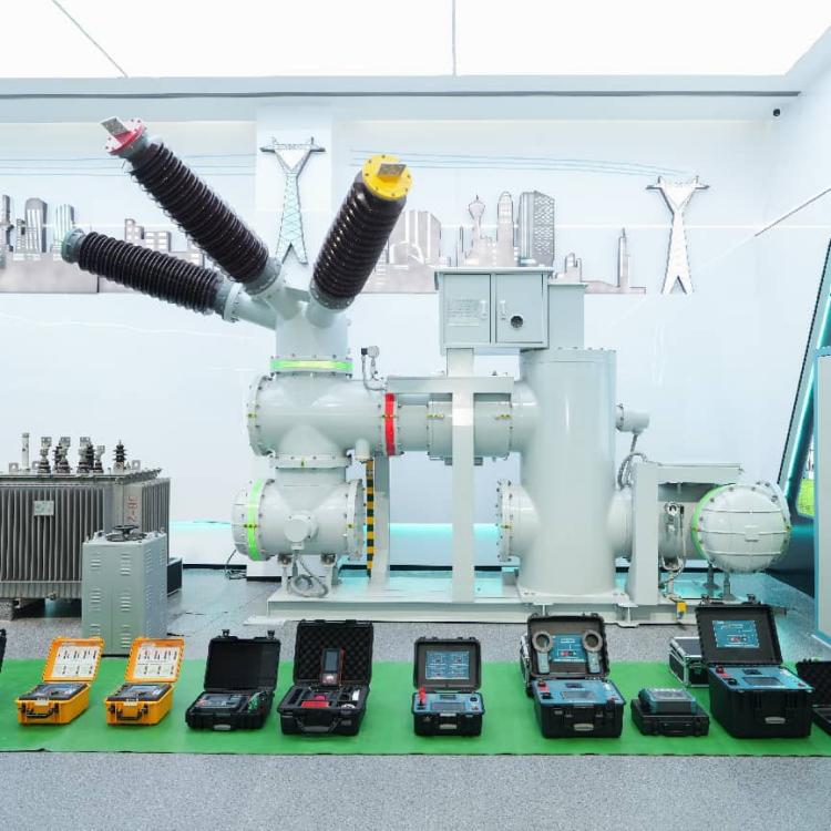
Weshine Electric Manufacturing Co., Ltd. is a professional high-tech factory specializing in the R&D, production, and calibration of high-current loop resistance testing instruments. With standardized production workshops, independent laboratories, and complete ISO quality management systems, all Weshine testers are strictly manufactured in compliance with IEC and DL/T industry standards. The factory implements full-process performance testing and calibration before delivery, ensuring stable current output, strong anti-interference performance, and high measurement repeatability for complex on-site power test environments.
The GDHL-200A/100A Intelligent Loop Resistance Tester is independently developed and mass-produced by the Weshine factory. Optimized for high-current, low-resistance field measurement scenarios, it features stable constant-current output, ultra-high test accuracy, and strong environmental adaptability, fully meeting routine inspection and preventive maintenance requirements for high voltage switchgear. The specific test current, accuracy, and compliance requirements should always be verified against the product documentation and the applicable local standards.
For high voltage circuit breakers, contact resistance testing should also be performed according to the relevant equipment standard and manufacturer’s maintenance requirements. IEC 62271-100 applies to AC circuit breakers used in high voltage systems above 1,000 V. IEC 62271-100
Standard Maintenance Requirements
Correct storage has a direct effect on the service life and measurement stability of a loop resistance tester.. As a professional power test instrument manufacturer, Weshine’s official factory maintenance specifications emphasize standardized daily storage and maintenance to avoid performance drift and extend instrument service life.
Store the Instrument in a Suitable Environment
The tester should be stored in a clean, dry, and well-ventilated area. The storage location should be free from:
1、Excessive humidity
2、Conductive dust
3、Oil mist
4、Salt spray
5、Corrosive gases
6、Direct sunlight
7、Extreme temperature changes
Moisture and corrosive contaminants may damage terminals, internal circuit boards, switches, and insulation components. Dust can also affect cooling paths and reduce the reliability of electrical connections.
Keep the Instrument Upright
Do not place the tester randomly in a wooden crate or stack heavy objects on top of it. The front panel should face upward during storage and transportation whenever possible.
This helps protect:
1、The display and control buttons
2、Output terminals
3、Internal transformer and circuit assemblies
4、Cooling structure
5、Protective enclosure
The instrument should be secured during transportation to prevent impact, vibration, or cable damage.
Use Moisture-Resistant Materials
When the tester is stored in a humid environment, place a suitable moisture-proof material underneath it. Do not allow the bottom of the enclosure to remain in direct contact with a damp floor or surface.
Before the next test, inspect the instrument for condensation. If moisture is present, allow the tester to dry completely before connecting it to a power supply or test object.
Three Common Testing Problems in the Field
1. Open Voltage Wiring Combined with Strong Electromagnetic Interference
An open voltage lead or loose voltage connection is one of the most common causes of abnormal readings.
Typical Symptoms
Depending on the site conditions, the resistance reading may show:
1、An over-range or infinite value
2、A highly unstable value
3、A value that changes when the test leads are moved
4、A result that appears normal but cannot be repeated
When a voltage lead is disconnected, the voltage-sampling circuit may not receive the correct signal. At the same time, a nearby energized busbar can create capacitive coupling and induce an unwanted differential-mode voltage in the open measuring circuit.
Possible Consequences
Strong interference may cause the tester to display an over-limit value. An inexperienced operator may incorrectly conclude that the circuit breaker has a serious contact-resistance problem and arrange unnecessary outage maintenance.
Milder interference may produce a value within the expected range. This is more difficult to identify because the result may appear valid even though the voltage connection is defective.
The measurement may then be incorrectly attributed to:
1、Poor circuit breaker contact
2、A damaged test clamp
3、An internal tester fault
4、An unstable power supply
Recommended Inspection
Before replacing the tester or removing the circuit breaker from service, check:
1、Whether both voltage leads are connected.
2、Whether the voltage clamps are firmly attached.
3、Whether the voltage terminals are clean.
4、Whether the current and voltage leads are correctly matched.
5、Whether the reading remains stable after reconnecting the voltage circuit.
6、Whether nearby energized conductors are producing interference.
A four-wire resistance measurement is only reliable when both the current circuit and voltage-sampling circuit are complete. Good contact at the test points is also essential because probe and connection resistance can affect low-resistance measurements. Megger low-resistance tester guidance
2. Oxide or Oil Film on Circuit Breaker Terminals
Circuit breaker terminals may develop an oxide layer, oil film, dust accumulation, or other contamination after long-term operation. This is especially common when equipment operates in a humid, polluted, or dusty environment.
Why It Affects the Test
The test clamp must make firm metallic contact with the terminal. If an oxide or oil film separates the clamp from the conductive surface, additional contact resistance is introduced into the test circuit.
This can affect the voltage-sampling path and create inaccurate or unstable results. The displayed value may not represent the actual resistance of the circuit breaker’s main contacts.
Possible symptoms include:
1、A resistance value higher than expected
2、Readings that change when the clamp is pressed or moved
3、Significant differences between phases
4、Poor repeatability
5、A sudden reduction after cleaning the terminal
Corrective Measures
Before testing, inspect the terminal surface and clamp jaws. Remove loose contamination using an approved cleaning method and make sure the contact area is dry.
The test clamp should be connected to a clean, firm, and mechanically stable surface. Do not rely on a loose clamp or a contaminated point merely because the instrument has started the test.
After reconnecting the leads, repeat the measurement. If the value becomes stable and consistent, the original abnormal result may have been caused by poor contact rather than by a circuit breaker defect.
Do not use abrasive methods that could damage plated terminals or change the contact surface unless the equipment manufacturer has approved the procedure.
3. Open Voltage Wiring Without Strong Electric Field Interference
An open voltage lead does not always produce an over-range reading. If there is no strong external electric field or capacitive coupling at the site, the amplifier may receive almost no differential-mode input.
In this situation, the instrument may display a value close to zero.
Why This Is Misleading
An inexperienced operator may interpret a near-zero reading as evidence that:
1、The tester has failed
2、The amplifier is damaged
3、The test current is not being generated
4、The instrument needs repair or replacement
The test may then be stopped unnecessarily. This can extend the equipment outage, delay maintenance, and increase the workload for the field team.
How to Identify the Problem
A near-zero or abnormal reading should be investigated before the tester is declared defective.
Check the following:
1、Verify the current output connection.
2、Confirm that both voltage leads are connected.
3、Inspect the voltage clamps and terminals.
4、Check whether the test circuit is complete.
5、Compare the reading with a known reference or a repeat connection.
6、Review the instrument’s self-test and alarm indicators.
7、Confirm that the displayed value changes normally when the test circuit is correctly connected.
A resistance measurement that suddenly drops to zero should not be accepted without checking the wiring. The result must be repeatable and consistent with the equipment condition and historical data.
How to Avoid Incorrect Judgments
When an abnormal loop resistance reading appears, field technicians should avoid immediately blaming the circuit breaker or the instrument. A systematic inspection is more reliable.
Use the following sequence:
1、Stop the test and confirm that the equipment is in a safe, de-energized condition.
2、Inspect the current and voltage wiring separately.
3、Check the clamp position and terminal cleanliness.
4、Look for nearby energized conductors and possible electromagnetic interference.
5、Reconnect the leads and repeat the measurement.
6、Compare the result with other phases and previous records.
7、Check the tester using an appropriate reference or verification method.
8、Only then determine whether the equipment or the tester requires further maintenance.
9、The displayed resistance value should always be considered together with test current, connection quality, ambient conditions, phase comparison, and equipment history.
Key Points for Reliable Loop Resistance Testing
The most important factors in field testing are:
1、Keep the tester clean, dry, and properly stored.
2、Use a complete four-wire connection.
3、Check voltage leads carefully before applying test current.
4、Ensure that clamps contact clean metallic surfaces.
5、Be aware of electromagnetic interference from nearby energized busbars.
6、Repeat suspicious measurements after correcting the connection.
7、Never diagnose a circuit breaker fault from one abnormal reading.
8、Follow the tester manual and applicable power industry standards.
Frequently Asked Questions
What can a loop resistance tester measure?
It can measure circuit breaker contact resistance, control switch loop resistance, busbar connections, cable conductor resistance, and welding contact resistance.
Why does the tester show an infinite resistance value?
An infinite or over-range value may be caused by an open voltage lead, poor clamp contact, an incomplete test circuit, or a genuine open circuit. The wiring should be checked before diagnosing the equipment.
Why does the reading suddenly become zero?
A near-zero reading may occur when the voltage-sampling circuit is open and there is little external electromagnetic interference. It does not necessarily mean that the tester is defective.
Can an oxide film affect contact resistance testing?
Yes. Oxide, oil, and dirt can prevent the test clamps from making reliable metallic contact and may introduce additional resistance into the measurement circuit.
How should a loop resistance tester be stored?
Store it in a dry, ventilated, dust-free area without corrosive gas. Keep the front panel facing upward and use moisture-proof material beneath the instrument when necessary.
Conclusion
Most abnormal loop resistance readings are not caused by a single factor. Open voltage wiring, poor clamp contact, terminal contamination, and electromagnetic interference can all distort the test result.
The GDHL-200A/100A Intelligent Loop Resistance Tester independently developed and produced by Weshine Electric delivers stable, high-precision measurement for on-site resistance testing. Backed by the factory’s strict quality control system, standardized calibration process, and years of power field application experience, the instrument effectively reduces testing errors caused by equipment performance defects. However, accurate and credible test results still depend on standardized field operation, correct wiring, and scientific maintenance management.
As a professional manufacturer of power test instruments, Weshine Electric provides one-stop solutions including instrument customization, factory calibration, technical guidance, and after-sales support for global power maintenance, substation inspection, and industrial power testing projects. Professional technical support and factory bulk supply services are available for engineering teams and enterprise purchasers.